This tutorial provides a basic introduction to actuators for quasi-static applications. This includes a description and comparison of the different actuator designs. The tutorial also describes how a piezoelectric actuator behaves under load. Finally, the tutorial concludes on three essential points to consider, when you select your actuator for a quasi-static application.
Different Actuator Designs
There are different ways of using the piezoelectric effect for actuator purposes: With bulk, multilayer (individual or stacked), benders or amplified actuators.
Definitions: Axes, Free Stroke, Blocking Force
There are a few definitions that are important to get in place in order to get the full understanding of actuators, actuator design and how to select the right actuator: Axes, free stroke and blocking force.
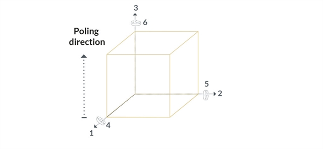
Axes
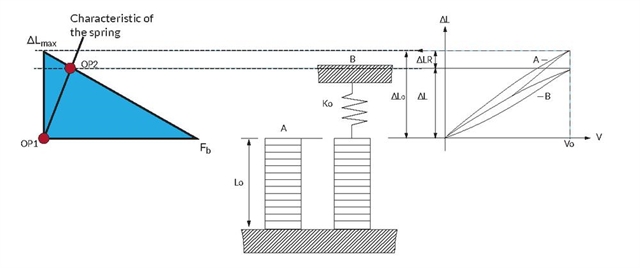
Similarly to most materials, piezoelectric ceramic is elastic, i.e. it follows Hooke’s law. In other words, strain is proportional to stress. In addition, the piezoelectric effect can be represented as an additional term in the relationship, in a first approach proportional to the electrical field. This can be visualized as a linear relationship on two axes. This ”bilinear” relationship is valid at the material or microscopic level (strain, stress, field) whatever the orientation of the material and can be extended at the macroscopic level to all types of actuators (displacement, force, voltage). As a result, any piezoelectric actuator can be described as a spring with a characteristic that can be shifted through the application of a voltage. Or in a displacement versus force graph.
Free Stroke and Blocking Force
It is an industry standard to describe this behavior using the terms ”free stroke” and ”blocking force”. Free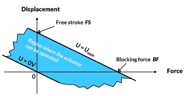 stroke is the vertical distance between the extreme curves (0 and Umax) while blocking force is the horizontal distance between the curves. Note that in this model, the stiffness of the actuator is (blocking force)/(free stroke) and is supposed constant. This characteristic might be limited by a minimum/maximum force allowable on the actuator. However, these parameters are not necessarily related to the blocking force.
Bulk Components
The most common configuration of a bulk component is with the electrodes perpendicular to the poling direction. Here, the application of an electric field on the surface electrodes will lead to a contraction in directions “1” and “2” together with an expansion in direction “3”. Bulk components are available as rectangular plates, discs, rings, tubes. As actuators, they provide micrometer displacement but require high voltage for operation (kV range).
Learn more about our bulk products
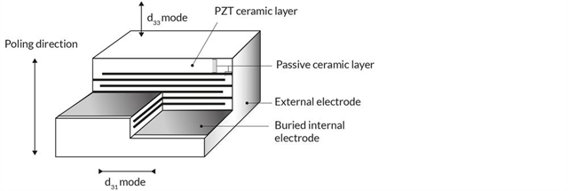
Multilayer Actuators
CTS plate and ring actuators can be used either in direction ”3” or ”1” similar to bulk components. The difference compared to bulk is that the active volume is divided into many thinner layers, allowing high electrical field under lower voltage. Free displacement is up to 5 µm with blocking force in the range 200 to 10000 N depending on material and cross-section.
Learn more about our multilayer products
Stacked Multilayer Actuators
CTS plate and ring actuators can be stacked in order to multiply the displacement. As a result, free displacement is proportional to the height of the stack. Blocking force is almost unchanged.
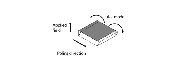
Shear Actuators
In CTS shear plate actuators, the electrical field is applied orthogonally to the poling direction. The resulting motion is a “tilting” motion leading to a translational movement in the plane of the electrodes. Shear plate actuators can be stacked in single-axis and multi-axis solutions.
Learn more about our shear products
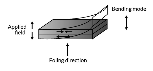
Bending Actuators
CTS bender plates and bender rings exploit the contraction in direction ”1” and amplify it through a bending motion. As a result, large free displacements can be achieved (up to the millimeter range).
Learn more about our bending actuators
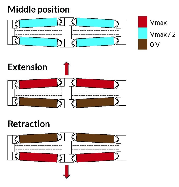
Amplified Actuators
In order to obtain even larger displacement, actuators can be coupled to an amplifying mechanical structure. The trade-off is a lower stiffness and blocking force. Many schemes can be found (lever, flextensional, hydraulic etc.). CTS’ own amplification mechanism is commonly called ”diamond frame” and is based on the differential expansion of two sets of multilayer stacks in a ”V” configuration.
Learn more about our amplified actuators
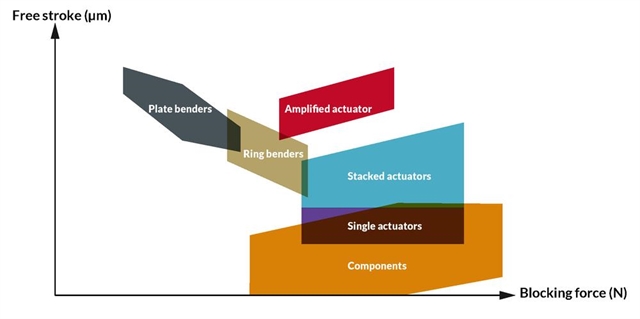
Comparison of all Actuator Designs
The different actuator designs provide a wide range of performance, each with their preferred characteristics. Blocking force and free displacement performance can be plotted on a graph for the different actuator families, providing an overview of available products. Custom designs can of course expand the plotted areas.
Behavior under Load
The load applied to a piezoelectric actuator plays a crucial role in defining its performance. At a given voltage, the model described in the section Different actuator designs defines a characteristic line on the displacement vs. force diagram, where the actuator could be. The actual operating point (force, displacement) depends on the load.
Constant load
For example, in the case of a simple positioning table where a piezoelectric actuator moves the table in the Z direction, the load is a simple mass. Upon initial loading, the element is compressed by the mass and the actuator moves (illustrated by the operating point moving from OP1 to OP2). After that, when voltage is increased from 0 to Umax in quasi-static operation, the force applied on the piezo element by the load is a constant force, i.e. a vertical line on the displacement vs. force diagram (the operating point moving from OP2 to OP3). The actuator can therefore generate a displacement (curve B) sensibly equal to the free displacement (curve A).
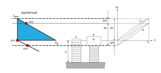
Spring load
In another ideal case, the load can be modeled by a spring. This spring has an elastic behavior, which can be represented on the displacement vs. force diagram by a straight line with a given slope. Upon actuation, the operating point of the system will follow this line (illustrated by the operating point moving from OP1 to OP2). The force applied on the actuator will increase as it expands. As a result, the actuator will generate a displacement (curve B) smaller than the free displacement (curve A) and a force lower than the blocking force.
A combination of loads
In the general case, the load is a combination, an arbitrary curve on the displacement vs. force diagram. The load can even vary during operation, so it might be a set of curves. When designing a piezo-based system, it is important to ensure that all load cases are covered so the actuator can deliver the required performance in all conditions.
How to select
When selecting a piezoelectric element for a quasi-static actuator application, the main parameter to observe is the load, i.e. the force vs. position characteristics of the load.
Start with force vs. displacement
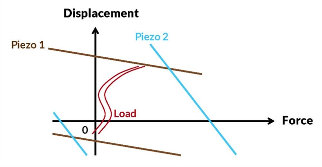
There might be a number of actuators that can fulfill the displacement vs. force requirements, i.e. whose characteristics include the load curve – as exemplified by “Piezo 1” and “Piezo 2” on the graph below. A first starting point for selecting candidates can be the comparison of the different actuator designs based on actuator blocking force vs. free displacement or stroke – to be found at the end of the section Different actuator designs.
What is the target for your design?
In order to choose from these options, it is important to know the optimization parameters. For example, is the target to optimize volume/mass, one particular dimension or stiffness/frequency response? In addition, there might be other requirements, such as environmental conditions, response time, drift. It is of course important to consider these requirements as early as possible in the design process in order to make sure that the objectives are met.
Operate in the best conditions
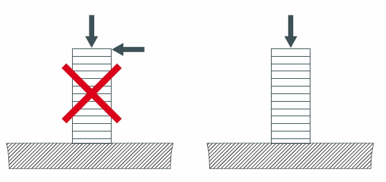
Finally, the actuator must be used in the best conditions. Typically, an actuator can tolerate a certain range of external force. For example, we do not recommend to use linear stacks in tension. This means that, if the load has to be both pushed and pulled, a preload must be added in parallel to the actuator, to make sure that the actuator is only submitted to compressive stress. Such a preload should be designed to have a stiffness much lower than the actuator (factor 10). This ensures that the preload does not ”divert” too much of the strain energy from the piezoelectric actuator.
DC Drive (static operation)
At low frequency, piezoelectric elements are essentially capacitors. Power is only required to change the voltage on the piezo element. The relationship of current and voltage for a piezoelectric actuator is the following:
I = dQ/dt = C x dU/dt
Where:
I=Current
Q=Charge
C=Capacitance
U=voltage
t=time
To maintain a piezoelectric actuator in its state of activation, only the leakage current has to be supplied. At temperatures well below the Curie temperature the internal resistance of piezoelectric actuator is in the order of 1010 Ohms. Consequently, under static operation virtually no current is drawn nor power consumed to maintain a state of activation (the high internal resistance reduces leakage current to micro-amp or sub-micro-amp range).